The Underside of the Tender, Loco and Draw-Bar
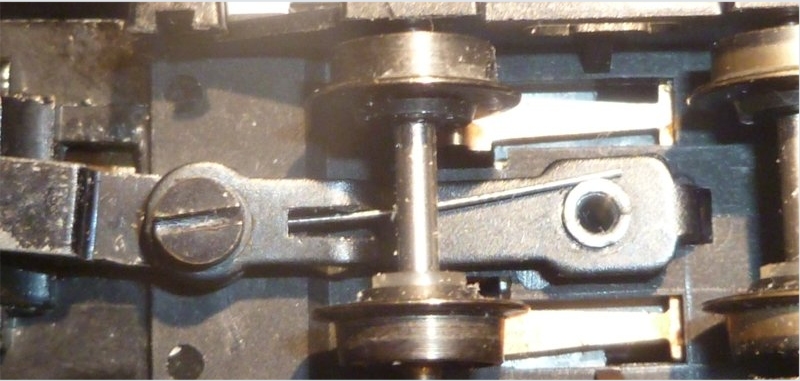
The loco is on the left in this picture, so the negative (left) side of the loco and tender is at the top of the photo.
You can see the clear plastic insulation on the right hand wheels at the bottom of the picture. This isolates the wheel from the axle and prevents the positive right hand side (top) from being connected to the negative left hand side (bottom) through the axle.
There is a wire spring which provides the electrical continuity between the loco body and the tender weight. The spring contacts the joining screw, although in the models that I have, the screw has a shoulder and doesn't tighten onto the eye of the spring. You should make sure that the electrical contact is sound though, parts have been known to have been painted where electrical contact is necessary. Even when brand new. The open end of the wire is sprung against the housing for the screw thread which protrudes from the bottom of the tender weight - as shown.
Grahame got in touch about a problem he was having. His 9F would work fine when going backwards, but was very erratic going forwards. The problem was traced to a poor electrical contact between the eye of the spring, and the middle joining screw which has accumulated a load of muck over the years. He managed to establish that electrical contact to the tender was broken when the tender and loco were pulled apart slightly when going forward, but contact was restored when pushed together going in reverse. Cleaning the middle joint solved the problem.
Maintaining Classic UK Minitrix Locos
The Minitrix trademark is currently owned by Märklin Inc.
Gebr. Märklin & Cie. GmbH, Stuttgarter Straβe 55-57, D-73033 Göppingen,
Baden-Württemberg
Website ©2002-2018
JFHeath