|
Wheels |
|
|
|
Work with the engine upside down such a manner that it cannot fall over, but so that it can be picked up and checked. Identify the wheel without the tyres and with the square hole. This is the centre driving wheel. Then, working from the right end to the left: Place the first wheel into its half round slot. and rotate it so that the hole is at the top (12 o'clock) position. Check that the gears mesh. If you have not removed the electrical pickup, check that the arm goes behind the wheel as you slot them into position. Slot in the second wheel (the one with the square hole). Drop it into an approximate position and make sure that the gears mesh. Check where the hole is and note which way the wheel needs to be turned to get the hole to the top. You now need to hold the right wheel in position, and rotate the centre wheel upwards around the cog until it becomes free of the axle slot. Now you will be able to count the number of teeth to the right or the left that you think is necessary, and then rotate the wheel back down the cog until the axle is in its slot. Check the hole positions again and repeat the process if necessary. The final wheel is inserted in a similar manner, except you have two wheels to hold in place. |
|
|
When you have finished, carefully place the plastic chassis bottom in place (hole to the rear, peg to the front), and insert the two screws to hold it in place. Place on a track and run it around by hand to check that the wheels roll smoothly. Return the wheels so that the holes are at the top, and check the alignment again, then rotate and check at the 3 o'clock, 6 o'clock and 9 o'clock positions. Do this from both sides. Finally, lay the chassis on its side and lay the coupling bar with its 3 oval slots over the screw holes in the wheels. The holes should be visible in the middle of each of the slots. |
|
|
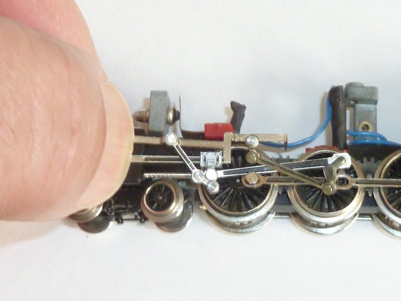
Use the two hexagon head screws to attach the coupling rod to the drive wheels. Be careful - they are fiddly and the screws are eaily lost. Take care not to cross thread them. I find that placing the screw in the hole of the coupling rod, and using this to offer the screw up to the hole, is the best way. Note that the little tabs on the coupling rod should point upwards. Applying light pressure with thumb or finger of the other hand, and turning clockwise, it is possible to get the thread started. This method gives more feedback through your fingers than any other I have tried, and the support from the couling rod means that the screw never falls over and drops into the engine. The second hole is done in a similar manner. Don't tighten the first screw, and use a thin screwdriver to support the end of the conrod as you use it to offer up the screw to the hole. Check that the motion is still smooth by pushing it around the track. |
|
|
Fit the motor. Make sure that the brass contact plate is seated correctly under the base of the motor, and you may wish to route the wires through the holes first - Black and green through the left hole, blue through the right. Leave the fastening screws for the time being. The motor isn't going to go anywhere. As soon as the worm gear engages, it is impossible to push the engine along a track. The wheels are locked. |
|
|
Route the wiring. If replacing the wire, you need very fine insulted wire. I used the coloured wire from screened hi-fi cable, but fine as it is, it is still thicker than the original. I'd start with the loco. Twist together a short length of blue (for the lamp) to a long length of blue (for the tender) and solder. Trim the soldered joint. Make sure the tab for the pickup is tinned with solder and solder the twisted joint to the tab with wires routed upwards away from the pickups. Take care not to let solder run down to where the moulding needs to sit. If you are fitting a capacitor, this needs to be soldered in - see below. |
|
|
If the pickup strip needs to have a blue wire soldered to it, then do this before fitting it into its insulating block on the chassis. Note that two wires are needed here (plus the capacitor). One wire goes to the tender, the other goes forward to power the grain of wheat lightbulb. Fit the drive wheel pickup using the plastic moulded insulating block. Take care to slot the arms behind the front and rear drive wheels on the right hand side of the loco. Secure in place with the screw. Slip a short length of insulating sleeve over the joint. If fitting the capacitor, the other leg needs to be soldered to the hole in the upright which can be seen in the photo above. |
|
|
Cut the short blue lead to length, remove the light connector strip from the plastic insulation (which may melt otherwise), bare a short end and solder to the light connector. Note that it is easier if the end of the wire points upwards when it is located. The insulated blue lead needs to be routed across the top of the screw valve gear insulation block, which is not yet installed. But see photo and how the lead fits into the weight. |
|
|
Note how the blue lead is routed to avoid the driving wheels, the worm gear and the motor itself. If you didn't route the leads through the holes at the back of the cab before, pop the motor out and do it now. Get the insulation sleeve on the spring to the motor brushes out of the way and solder the black lead to the bottom connector and the green lead to the top connector. Replace the sleeve to prevent the spring shorting out the two halves of the motor. Solder the brass base plate on which the motor sits to the bottom connector, if it isn't already in place. |
|
|
Bring the leads out of the rear of the cab in a loop This prevents the springiness of the wire from interfering with the tender as it is running round bends in the track. |
|
|
Route wires as shown. Cut to length, bare the ends and solder from the other side. |
|
|
The soldered joints may need to be filed down a bit. Ensure that the spring is in position, and the insulating layer and fit the circuit board under the tab at the right hand end, and secure with a screw at the left. The wires emerge from the tender through the coal hole. Make sure that you do not trap the leads when re-attaching the tender body - which has a screw and a small spring washer. Form the loop in the wire between tender and loco and twist to help it retain its looped shape. |
|
Balance the weight on the loco (help it with a bit of tape if necessary) and give the loco a test run. It will look odd, and won't go round corners properly, and the tender will be being dragged along by the leads. But it is just to check that the electrical connections are sound. |
|
|
|
Invert the loco and delicately remove the baseplate. Take care not to disturb the wheels. Place the rear bogie over the metal pin in the chassis. |
|
|
Rest the front bogie in position. Note the elongated slot - it does not coincide with any hole that you may see in the chassis. The bogie just rests there. When you replace the baseplate, make sure that the pin at the front fits through the slot in the front bogie. The hole at the back of the plate slots over the rear bogie pin. Fit and tighten the screws. If you separated the tender from the rear bogie, find the screw and reattach it. Now attach the weight again, and give the loco a proper run. If anything is untoward now, it needs to be fixed before the valve gear is reassembled. |
|
Valve gear |
|
|
Don't rush this. Slow, methodical and patience get the job done. You need more smaller fingers than you have. And you need a small screwdriver, a pair of thin pliers and a pair of tweezers handy. Bits will move around as you manipulate everything into position, and you need these tools to bring them back into line. Get the valve gear for the left side of the loco. |
|
|
|
The photo shows the wrongly assembled valve gear for the left hand side. Front is on the left of the photo. The slider carrying the round piston rod is too close to the front, it needs to be manipulated so that it is closer to the rear of the vertical linkage. But read on before trying to do that. The slider is made of plastic and will break if any force is applied to it. |
|
|
From the rear with the conrod and piston in place, but the slider is still too far forward in this shot (and wrong). |
|
|
The same linkage from the rear. Note the conrod (connecting the piston rod to the centre wheel) has a small hole and a large hole. The small hole slides over the end of the round piston rod. The black face should be outwards.
With the slider in roughly this position, it is possible to move the
linkage so that the upper left rivet of the cluster of 3, moves
behind and to the right of the hole containing the round piston rod.
This is made much easier if |
|
Correct |
Correctly assembled valve gear. Compare with the top photo in this section of the wrongly assembled gear. In this shot I have inserted the square peg in the round hole (which is how it will be eventually) but the chances of keeping it like this while you manipulate the rest of the gear is virtually nil. However. lay the assmbled gear on the side of the loco with everything roughly in the right place. It is worthwhile trying to get the end of the piston rod into the hole in the cylinder. A dressmakers pin or needle through the crank hole in the wheel may be useful to keep the end of the conrod in place. This will stop it from sliding down the piston rod and becoming free while you are not looking ! |
|
|
Here we are. Trapped. The phone will ring at this point. Ignore it. Note the piston rod is inserted into the hole in the cylinder, and the two slide bars are located in the corresponding grooves which are in the plastic moulding above the cylinder (under my thumb). The conrod and the eccentric rod are just flapping around at this stage. You need to keep hold with your thumb, and place the loco upright. And you need to try to prevent the conrod from sliding down the piston rod. Rest it on the centre wheel and use the coupling rod as a shelf to stop it from falling |
|
|
The insulating moulding which supports the slide bars. The right most half goes onto the chassis first, the end of the slider bar fits in the slot and the left hand moulding fits on top. |
|
|
Like this. |
|
|
And then like this. All of this is done one handed while you hold the other end of the valve gear in place. At some point you will decide to use sticky tape to give you another hand. Secure the end of the slide bar by loosely fastening the screw in the moulding. |
|
|
Time to fit the square peg through the round hole at the end of the conrod. Use a small screwdriver to support the conrod to keep the hole away from the wheel. This makes it easier to drop into place. Keep the support there to guide the square peg over the square hole in the wheel. There are four ways in which this will fit, Look at the photo. The rivet needs to be almost over the centre of the axle. Light pressure with the side of another small screwdriver blade will secure the mechanism. Don't push it all the way home yet - just enought to keep it in position. |
|
|
The other side is done in exactly the same way. You will need to unscrew the bolt that holds the slide bars in place and then gently lift the top moulding to introduce the right hand slide bar. An extra pair of hands or sticky tape to hold the other end in place is a must really. |
|
|
Check both sides visually and look from above to make sure that no part of the gear is going to catch on another part. It should look like the picture on the left. |
|
|
Fitting the body. You need to fit the weight and then remove the tape and return to holding the slide bars in place between finger and thumb. Fit the body by offering it from the front with the rear of the body raised by about 45 degrees. The objective is to get the side of the cylinders around the place where your finger and thumb are holding the slidebars. Check both sides. Once they are trapped, the front can be lowered and moved backwards slightly. Once in place, the back can be lowered. Don't push the cab down until the cylinder block is completely covered by the side cover on the body moulding. |
|
|
Hmm. I suppose we had better fit the screws to hold the motor in place, and push home the two square pegs that hold the conrod and the eccentric valve rod in place, and secure the motor with the two countersunk screws. |


Maintaining Classic UK Minitrix Locos
The Minitrix trademark is currently owned by Märklin Inc.
Gebr. Märklin & Cie. GmbH, Stuttgarter Straβe 55-57, D-73033 Göppingen,
Baden-Württemberg
Website ©2002-2018
JFHeath