| The first step is to create a sound base into which can be screwed some small screws. The ones shown are TurboDrive 2.5x10mm with a Pozidrive head. These are self tapping, and in theory, do not need a pilot hole, but they are so close the edge of board that a small pilot hole is recommended. I have previously marked the position of the rails, and the cork underlay has been cut back. The soldering iron is quite capable of charring the cork, and I discovered that it will quickly turn into glowing embers. Not a good idea. |
| It is essential that the baseboard halves cannot move against each other. I find these brass locating dowels ideal - there is a little movement in them, but by the time you have 4 along the length of the joint, all movement is eliminated. It is a good idea to have the dowels directly underneath where the rails are to join. |
|
This photo shows the underside of Code 55 track. One side of the
plastic web has a gap every 4 sleepers. The other side has no gaps at
all, although every 8the sleeper has a 'pinch' in the plastic to provide a
little more flexibility. This results in a number of characteristics
which are different from the code 80 streamline track:
|
|
Do Minitrix locos run on Peco Code 55 rail ?
Yes they do. There is some concern that the large flanges catch on the sleepers, or have problems on the pointwork when the rolling stock run on the flange as the wheels cross the gaps. I did a lot of experimenting with this, and have found no such problems so far. The photo a cross section of one of the rails which is embedded firmly in the underlying plastic. Not only does the rail have a lower profile as a result, but it is much more firmly attached to the underlying plastic 'frame' and sleepers. |
|
About 4 sleepers need to be removed at the baseboard joint so that the rail
can be soldered to the screw heads. The screws need to be driven in so
that there is the tiniest of gaps between the underside of the rail and the
screw head. The join in the baseboard needs to be separated with the new track positioned loosely over the screws - here I am using a 15" radius TrackSetta to provide the spacing. Bits of card work just as well. |
| The rail needs to be fitted in place before any soldering at the baseboard joint is carried out. Here I am cutting one end of the rail to fit onto the points - leaving a little room for the insulation part of the insulating rail joiners. Err on the long side when cutting - it is easier to grind the rail end shorter than it is to add a bit. |
| The cut rail - looking a tad short, but the insulating joiners have a little tongue of plastic which prevents the rail ends from making an electrical connection. A small gap between rail ends is no bad thing - it allows for a little heat expansion |
| This picture shows a section of the sleeper bed with the rails removed. The rail is held in place along the entire length of the track, rather than being held just at the sleepers as is the case with code 80. |
| At the other end, two metal rail joiners have been slipped onto the right hand rail (two sleepers have been removed). The two ends are lined up - I find it easier to elevate both ends. The rail joiner is protruding slightly so that the left hand rail can be dropped onto it. The joiner is then pushed from the right with a pointed scribe. With code 55, this is much easier as there is a small channel to guide the point, and it can be pushed from either the inside of the rail or the outside. Once partly located, the support (another bit of TrackSetta) can be removed before the joiner is slid so that it is positioned equally on either side of the joint. |
|
The rails in place with the joint out of sight at the bottom right of the
picture. The 3 rails feed into a complex consisting of a 3 way point
and a left hand point. Insulating rail joiners are used at this end as
the frogs are live and have polarity changing switches fitted to the point
motor. The 3 tracks are loosely fitted to the pointwork, across the
baseboard joint to another complex on the adjoining board. Each track
is cut to precisely the correct length as one piece - although having one
piece is not essential. The carriage is a very early (1982) Farish coach with metal wheels with large flanges. The front bogey always rides the points well. The rear bogey will come off if there is anything wrong with the trackwork. If the track isn't foolproof at this stage, then it cannot hope to be foolproof after the track has been separated at the baseboard joint. |
| Here is the baseboard joint with the track laid loosely, but fitted at both ends to the pointowork. Note that on this shot, the track is slightly elevated and the sleepers are not on the cork bed. A final check of this and the height of the screw heads is important. I use spots of superglue to tack the track bed to the cork, and hand dumb-bell weights to keep the track near the joint positioned properly. A smear of flux on the screw heads is useful too. |
|
Here is the rail soldered. It looks a mess - partly because of the
flux. A hot soldering iron with a larger tip is to be recommended -
the screw has to get hot enough to melt the solder. Note that some
melt damage is likely to the sleeper nearest the screws. The screw and
the rail get hotter if there is solder already on the soldering iron tip.
The tip is chamfered to a chisel edge and I place one side of the tip flat
onto the exposed half of the screw head on the outside of the rail. I
then feed solder between the rail and the top side of the soldering iron.
Once I can see solder flow underneath the rail to the screwhead on the
inside of the rail, and that solder has spread along the outside of the
rail, I can remove the iron. The track should not be moved until the
solder has set - this can take a couple of minutes.
Note the outside of the rail has a large blob of solder. The inside just has solder flowing underneath the rail. Note the scorching around where the screw enters the wood. |
|
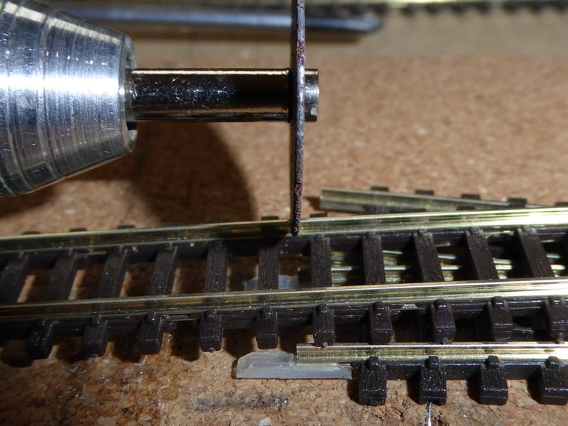
A hobby drill with a cutting disc is used to cut through the rails.
The yellow TrackSetta spacer has been removed, and the ends of the rail have
been ground down. I dont use a file for this as it can move the
screws. Grind a bit. Test the gap. In theory, the rails should line up perfectly. In practice, they won't. The boards have been separated and repositioned and if the rail was not tacked properly, it is possible for the rail exhert a small amount of strain - which goes un-noticed until the two halves have been cut through. Then one of the 'springs' free. Just a little, or the screws will have turned slightly. As is the case with a couple of the joints in these photos. Re-positioning with a hot soldering iron is possible, although there is a limit to how often you can do this without scorching the wood too much. All of these joints are now spot on. A bit of needle file work on the top and inside of the rail smartens it up and removes any burrs. Check with a metal wheeled bogey - press it onto the track as you wheel it over the joint. Check for one rail slightly raised, and also push it to one side of the track and then to the other to feel for any 'bumps' there. Although it looks an untidy mess, the track joint is firm, solid and allows the boards to be separated and rejoined easily. It will all be hidden by the ballasting. One more point. Make sure that the track a few cm away from the soldering is firmly pinned or glued down. If the track moves it will rotate the screw slightly and re-introduce bumps. |


Maintaining Classic UK Minitrix Locos
The Minitrix trademark is currently owned by Märklin Inc.
Gebr. Märklin & Cie. GmbH, Stuttgarter Straβe 55-57, D-73033 Göppingen,
Baden-Württemberg
Website ©2002-2018
JFHeath